The regulation box ── design within constraints
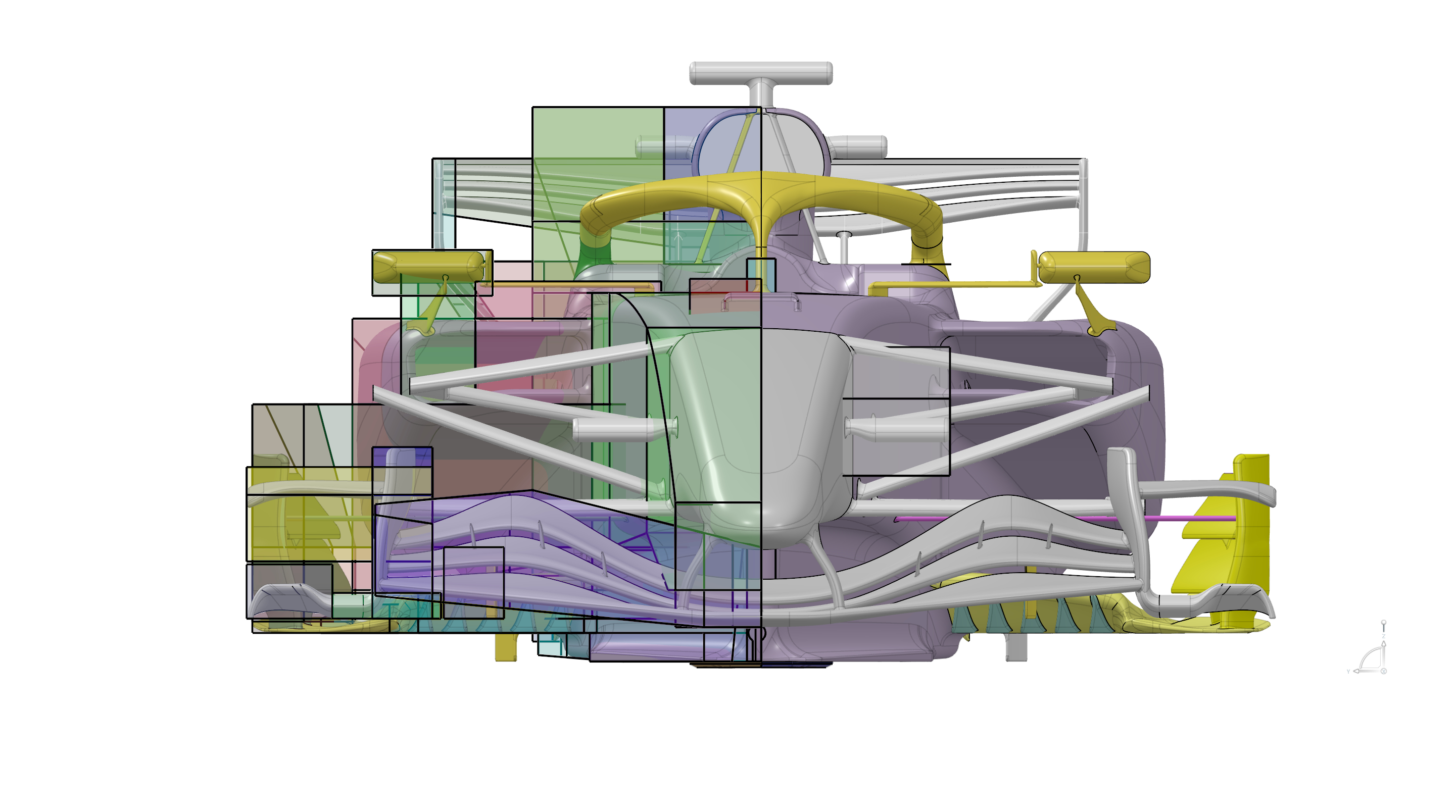
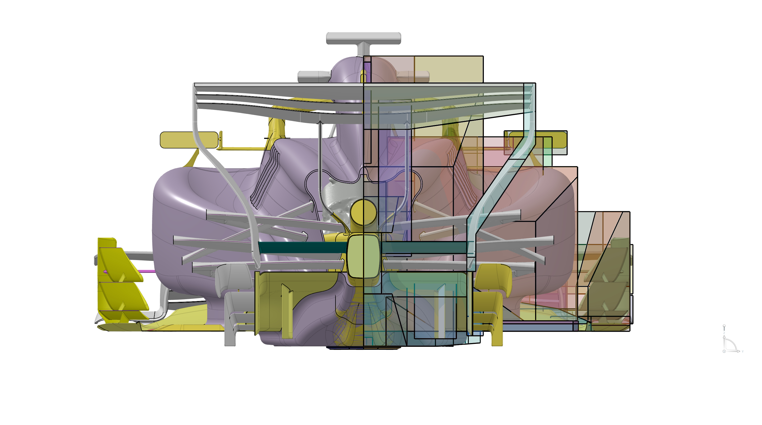
Every aerodynamic part of a formula car must fit inside a “box” defined by the regulations. Front wing, bargeboard, floor, rear wing — each device has a strictly defined allowable region (volume), and the engineer may design the shape freely only within that constraint.
The regions shown as colored translucent boxes in the images above are the zones permitted by the regulations. On modern formula cars this freedom is quite restricted, and as a result every team’s car ends up with a similar silhouette. Yet even within the same box, the crafting of details — the treatment of endplates, the shape of the floor edge, the placement of vanes — greatly influences aerodynamic performance.
What to “look at” in CFD ── two indicators, CpT and Cp
When “visualizing” CFD results, the physical phenomena that emerge differ completely depending on what you express as color.
Cp (pressure coefficient) ── the “pressure difference” that generates downforce
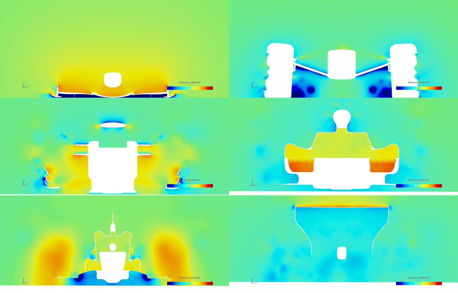
Cp (Pressure Coefficient) is a dimensionless number expressing how much higher or lower the static pressure at a point is relative to the free-stream dynamic pressure. When negative pressure (blue regions) spreads over the underside of a wing or floor, a suction force toward the road — that is, downforce — is generated. Conversely, positive pressure on the underside (red/orange) acts to push the car up off the road, so in downforce design the key is how wide and strong you can keep the negative-pressure region on the underside.
The image above animates the pressure distribution of each section while slicing the car from front to rear like a CT scan. You can read how strong blue (negative pressure) forms on the underside just behind the front wing, and how that negative-pressure band is maintained as the flow passes beneath the floor.
CpT (total pressure coefficient) ── the “energy quality” of the flow
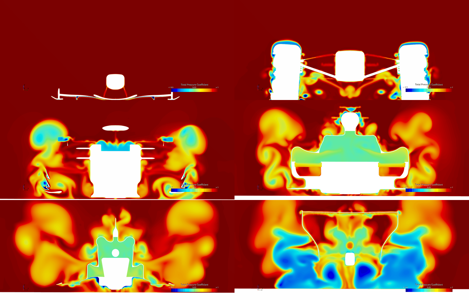
CpT (Total Pressure Coefficient) is a coefficient based on “total pressure,” the sum of static and dynamic pressure. Because fluid that has lost energy through viscous friction or turbulent mixing has lower total pressure, the CpT map directly shows the energy of the flow. The blue regions spreading behind the tires and suspension arms are exactly the wake — a mass of low-quality air that has lost its energy.
Whereas Cp shows “where downforce is being generated,” CpT is an indicator for evaluating “how healthy the air heading toward the floor is.” Comparing Cp and CpT on the same section lets you verify the aerodynamic design from both the pressure-generation and flow-quality perspectives, which is why these two indicators are used together in modern CFD aerodynamic development.
Why the wake is visible in CpT: In an ideal inviscid flow, energy is conserved, so CpT takes a constant value. In real flows, however, total pressure drops irreversibly due to viscous friction at the tire surface, boundary-layer separation and momentum dissipation by turbulence. Low-CpT (blue) regions are precisely these “traces of energy loss,” and the more this low-CpT region spreads at the floor inlet, the more downforce efficiency falls.
Visualizing the tire wake
As stated in the previous article, the wake (turbulence) produced by the front tires significantly degrades the quality of the air flowing beneath the floor. So what does the tire wake actually look like? Let us visualize the total pressure coefficient (CpT) from CFD on a section.
Each CFD image below is shown as a two-row comparison. The top row is a spec with weak wake countermeasures and the bottom row is a spec with strengthened wake countermeasures. In the total-pressure-coefficient color map, red regions indicate healthy flow that retains its energy, and blue regions indicate low-quality flow that has lost energy (the wake).
Around the front suspension ── the source of the wake
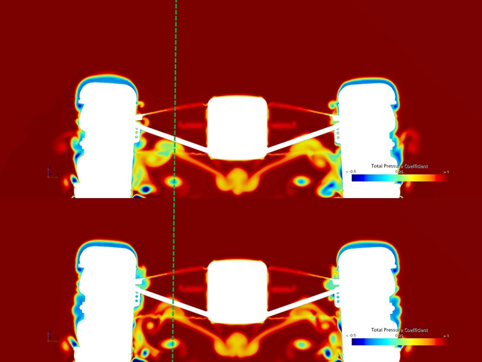
Looking at the section just behind the front tire, a vast blue region — the wake that has lost its energy — spreads behind the tire and suspension arms. The wake generated from the lower half of the tire (near the contact patch) in particular has the most serious impact, because it flows straight toward the floor inlet.
In the strengthened-countermeasure spec (bottom row), the wake region at the lower part of the tire (blue region) is clearly smaller, and the proportion of clean air flowing into the floor inlet increases. This difference directly affects the efficiency of the underfloor’s Venturi effect.
Around the rear ── downstream propagation of the wake
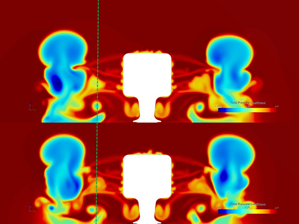
Tracking further downstream to near the rear tires reveals that the wake generated at the front propagates rearward along the sides of the car, affecting the rear aerodynamic environment as well. In the strengthened-countermeasure spec (bottom row), the wake structure is more organized, and the quality of the flow reaching the rear of the floor and the diffuser is improved.
Around the cockpit ── flow over the upper body
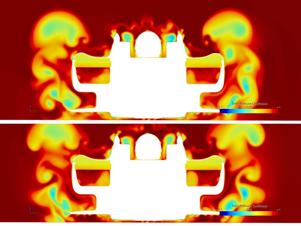
The section around the cockpit shows the quality of the flow passing over the upper body. Wakes also form behind the induction pod, mirrors and halo, but if the wake countermeasures around the front are working well, the quality of the flow passing along the sides of the car improves too, raising the quality of the inflow reaching the rear wing.
What is a streamwise vortex?
So what, concretely, is the “weapon” for managing the wake? It is the streamwise vortex.
A streamwise vortex is a vortex structure that rotates about an axis aligned with the main flow (the car’s direction of travel). Whereas ordinary vortices — wingtip vortices or Kármán vortices, for example — are often “transverse vortices” with axes perpendicular to the main flow, a streamwise vortex rotates helically along the flow direction.
The most important function of this streamwise vortex is its ability to entrain and move the surrounding flow. As the vortex rotates, it lifts fluid upward on one side and pushes it downward on the other. Using this entrainment effect, it becomes possible to “drive” a low-energy flow such as the tire wake in a specific direction.
Forming the mushroom shape: When streamwise vortices are deliberately generated from the front wing’s endplates and vanes, they act on the low-energy region of the tire wake and deform its cross-sectional shape. When working ideally, the wake’s cross section is shaped into a mushroom shape. By pushing the lower part of the wake outward and lifting the upper part, the streamwise vortex moves the low-energy region near the tire’s underside away from the floor, securing clean, high-energy flow at the floor inlet.
In other words, the essence of wake management via streamwise vortices is not to “erase” the wake but to “change its shape and move it to a position where it does no harm to the floor.” By reducing the wake region at the tire’s underside, the air flowing beneath the floor becomes clean, maximizing the underfloor’s downforce performance.
A history of the streamwise vortex ── the innovation of the 2010s
The concept of deliberately generating streamwise vortices to shape the wake was fully adopted into formula-car aerodynamic development only from the 2010s onward. Wingtip vortices and bargeboard vortex structures existed before that, but the idea of systematically incorporating streamwise vortices into the design as a “tool for wake management” was made possible by dramatic advances in CFD technology and the growth of computational resources.
On today’s F1 cars, the front-wing endplates, the cape under the nose and the complex fin arrays of the bargeboards are all devices for generating precisely controlled streamwise vortices. The strength, position and rotational direction of each vortex are designed to optimize the shape of the wake at the floor inlet.
Potential application to road cars and GT cars
Interestingly, this way of thinking about wake management using streamwise vortices is still barely reflected in road-car aero parts. The aerodynamic parts of road cars and GT cars center on direct downforce generation by wings and spoilers, and the approach of actively controlling the flow structure with vortices is not yet common.
Yet this technology, proven in the world of formula cars, holds the potential to greatly improve the aerodynamic efficiency of road cars and GT cars if applied appropriately. In particular, there are plenty of areas where it could be applied — managing the tire wake emerging from the fenders, improving the flow quality of the underbody, and more.
Interested in aerodynamic design using streamwise vortices, or in optimizing wake countermeasures through CFD analysis?
SYNSETECH provides the fluid-control expertise cultivated in formula-car development
to the aerodynamic development of road cars and GT cars as well.
SERIES — Downforce of the modern formula car
① Sources of downforce
② Dealing with tire wake (this article)