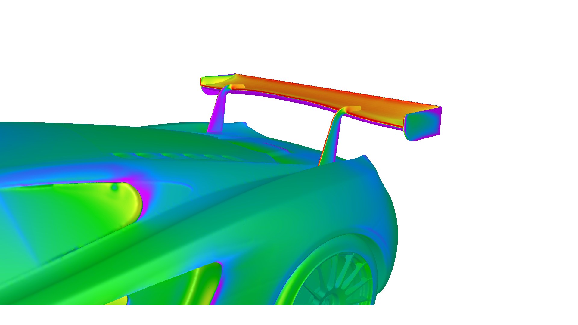
The rear wing is a “lump of drag”
There is a fact to recognize first. The rear wing is the part with the largest drag penalty of all the aerodynamic parts that make up a race car.
A wing bends the airflow with its airfoil and generates downforce through the pressure difference between top and bottom. But bending the airflow inevitably produces induced drag, to which are added the friction drag of the wing surface and the form drag of the stays and endplates. Compared with a front splitter or diffuser, its drag per unit of downforce is overwhelmingly larger. That is precisely why it is a part where “how you use it” is put to the test.
Judging circuit characteristics is paramount: On circuits with long straights where top speed matters, lay the wing down to reduce drag. On technical circuits with a succession of medium- to high-speed corners, stand it up to prioritize downforce. Finding the optimum of this trade-off is the essence of wing setup.
Understanding the polar curve
To evaluate a wing’s performance correctly, an understanding of the polar curve (lift-drag curve) is essential. The polar curve is a graph plotting the drag coefficient (Cd) on the horizontal axis and the downforce coefficient (-Cl) on the vertical axis — a tool for visualizing a wing’s aerodynamic efficiency.
L/D ratio — the indicator of aerodynamic efficiency
The slope of the tangent drawn from the origin to the curve on the polar plot represents the L/D ratio (lift-to-drag ratio = aerodynamic efficiency). The point where this tangent touches the curve is “L/D max” — the point of maximum downforce per unit of drag. The apex of the curve, meanwhile, is “DF max” — the point of maximum absolute downforce.
In motorsport aerodynamic theory, the region from L/D max to DF max is the wing’s operating range. On circuits with long straights where top speed matters, you emphasize efficiency toward L/D max; on technical circuits with a succession of medium- to high-speed corners, you chase maximum downforce toward DF max. Where within this range you operate is the heart of the per-circuit setup.
Conversely, in the region beyond DF max (the stall region), downforce decreases while drag alone keeps increasing, so it should not be used on any circuit. And in the low-angle-of-attack region before L/D max, the wing’s capability is not being fully drawn out.
Use it between L/D max and DF max. A wing’s operating range is the region bracketed by these two points. Toward L/D max if you want straight-line speed, toward DF max if cornering speed is the top priority. In either case, not entering the stall region is an absolute requirement for a race engineer.
The importance of the suction side and flow separation
Most of a wing’s downforce is generated by the suction side (low-pressure surface = underside). The pressure side (upper surface) contributes at most about 30–40% of the total, while the remaining 60–70% comes from the low pressure on the suction side. In other words, it is no exaggeration to say that the quality of the suction-side flow determines wing performance.
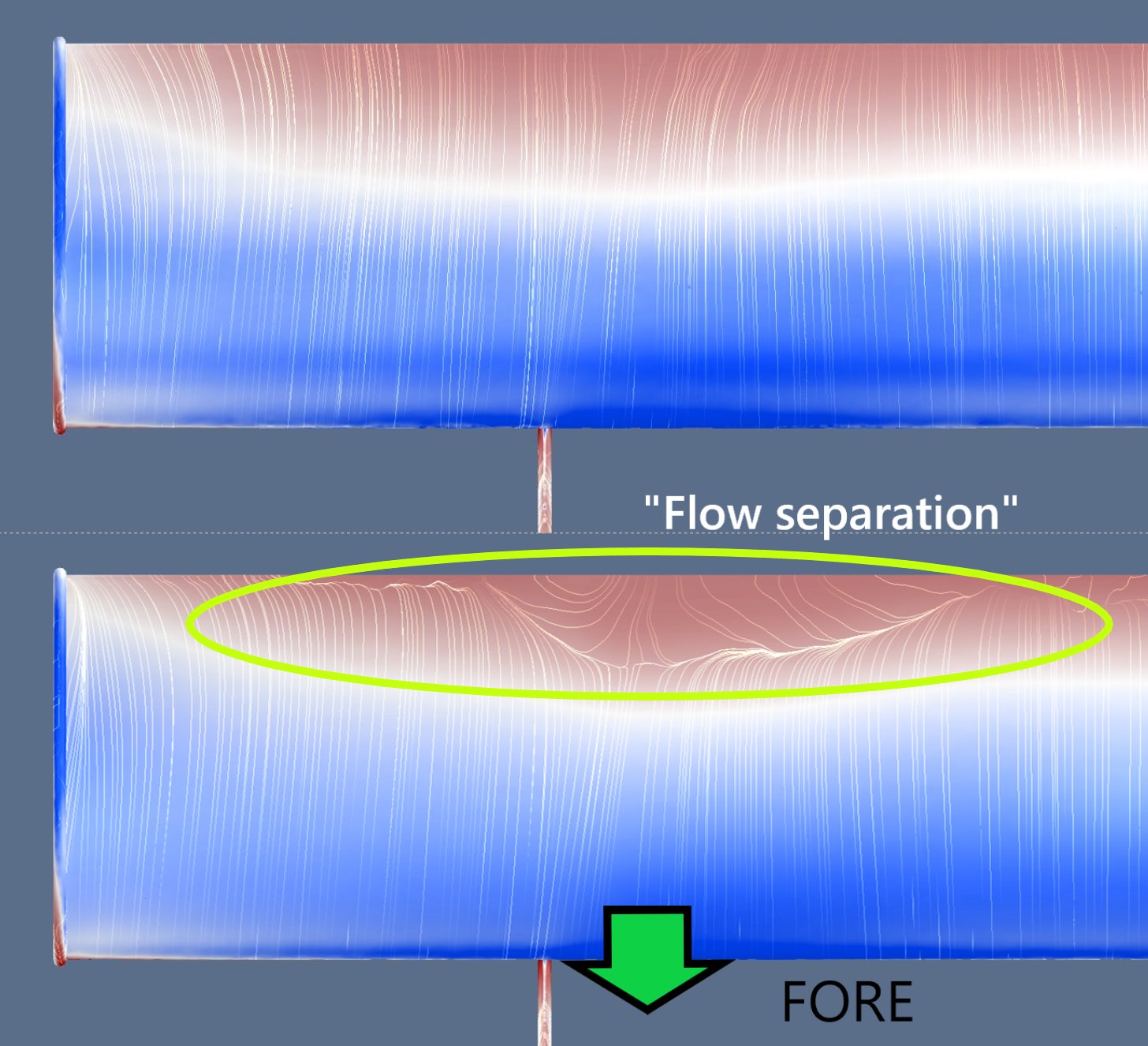
Why does flow separation occur?
On the suction side, a sharp pressure recovery (adverse pressure gradient) occurs from the leading edge toward the trailing edge. When the boundary layer can no longer withstand this adverse pressure gradient, the flow leaves the wing surface — this is flow separation. The main factors that cause separation are as follows:
Main factors that cause flow separation:
① Excessive camber — the suction-side pressure gradient becomes too steep
② Excessive angle of attack — beyond the stall angle, separation progresses rapidly from the trailing edge
③ Abrupt curvature changes — the boundary layer separates where the wing-surface curvature is discontinuous
④ Surface dirt, debris and steps — bug strikes, tape edges and scratches also locally disturb the boundary layer and trigger separation
What happens when separation occurs
When flow separation occurs, it does not stop at simply reducing downforce. The problem is more serious.
Separation does not necessarily occur uniformly across the wing’s span. When it occurs on only one side or only in the center, the downforce distribution becomes uneven, and the car’s yaw moment (the force about the turning axis) and pitch balance change. When this happens mid-corner, the driver feels the rear grip suddenly let go.
What is even more troublesome is that separation appears and disappears intermittently depending on speed and vehicle attitude. If downforce changes unpredictably every time the pitch changes under braking, it is impossible to win the driver’s trust. Degraded drivability — this is the most serious consequence a low-performance wing brings.
Conditions for a high-performance wing
Given the discussion so far, the conditions for a high-performance wing become clear.
1. Usable within the operating range from L/D max to DF max
It must have an airfoil and setup range that allows selecting an appropriate angle of attack — from efficiency-focused (toward L/D max) to maximum-downforce-focused (toward DF max) — according to circuit characteristics. A wing that enters the stall region, or one with a narrow adjustment range usable only under specific conditions, cannot be called high-performance.
2. No flow separation on the suction side
The airfoil’s curvature distribution must be smooth, and attached flow on the suction side must be maintained within the operating angle-of-attack range. This depends not only on airfoil design but also on the quality of the surface finish — the molding precision of the CFRP and the condition of the clear coat.
3. Robust against changes in vehicle attitude
When braking, acceleration and lateral G change the car’s pitch and roll, the wing’s effective angle of attack also varies. It must maintain stable aerodynamic characteristics within this range of variation — that is, it is important that the performance curve’s slope is gentle and free of abrupt changes in behavior.
4. Setup can match circuit characteristics
It must have an adjustment range to minimize drag on speed-focused circuits and maximize downforce on corner-focused ones. Flexibility at the track — angle-of-attack adjustment, adding or removing a Gurney flap — is also part of design quality.
In SYNSETECH’s contract CFD analysis, we provide end-to-end support through numerical analysis with CFD tools — from evaluating wing-airfoil performance and generating polar curves to quantitatively assessing the risk of flow separation on the suction side. “A wing that produces downforce but that, for some reason, the driver can’t trust” — we identify the cause from flow-field visualization and propose improvements.
Summary
The rear wing is the part with the largest drag penalty on a race car. That is precisely why it demands choosing a point that matches the circuit characteristics within the operating range from L/D max to DF max, not letting the suction-side flow separate, and maintaining aerodynamic characteristics that are robust against changes in vehicle attitude.
A high-performance GT wing is not simply a wing with large downforce. Producing the necessary downforce with the minimum drag, and giving the driver predictable behavior under all driving conditions — that is the essence of a high-performance GT wing.
← Back to blog list